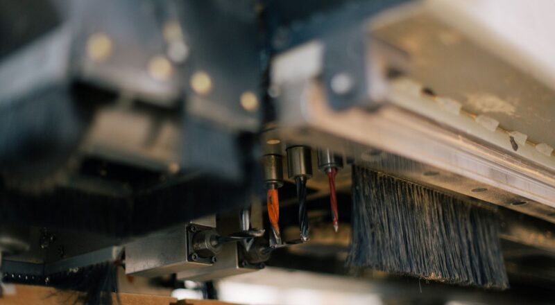
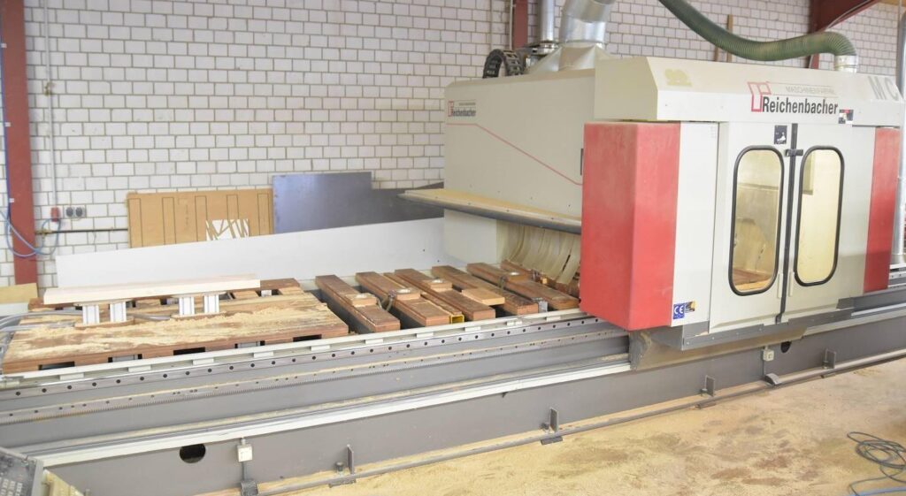
The starting point for this next project was a defect in one of our CNC portal milling machines at my workplace, which is used for manufacturing staircase components. The defect did not directly involve the production system itself, but rather the projection laser used for setting up the vacuum clamps and for positioning the workpiece on the milling table.
A conversation with the manufacturer revealed that the projection laser had already been discontinued and there were no longer any spare parts available for it. The only solution would have been a custom-made replacement, as the machine control only had an outdated RS232 interface, which was no longer installed by the manufacturer as a standard feature.
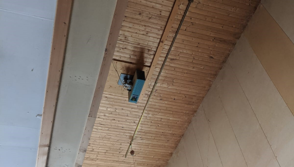
Considering the relatively high cost of several tens of thousands of euros for a new projection laser and the challenging circumstances involved in assembling and disassembling the laser system at around 6m from the ground, I opted for a software solution.
In addition to the aforementioned points, an application for calculating the positioning of the workpiece and vacuum clamps provided a speed advantage, as it could also calculate the necessary zero-point shifts. Normally, the workpiece would be placed at a location determined by the CAM software and then manually adjusted due to the complex shape of the machine table. This trial-and-error process typically consumed a significant amount of time.
Importing the G-Code
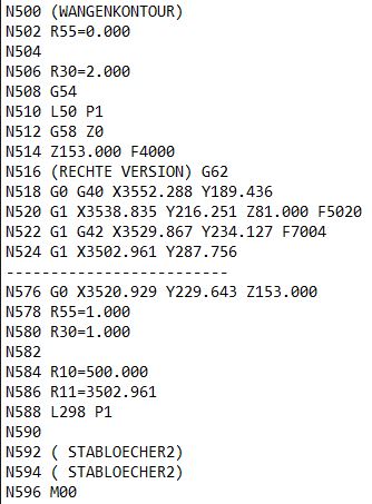
As a first step, it was necessary to read the G-code files into the development environment and locate the lines that defined the contours of the workpieces. To do this I leveraged the start and end strings that the CAM software provided. (WANGENKONTOUR) or (AUFG AUSSENK) as the start flag and M00 as the end flag.
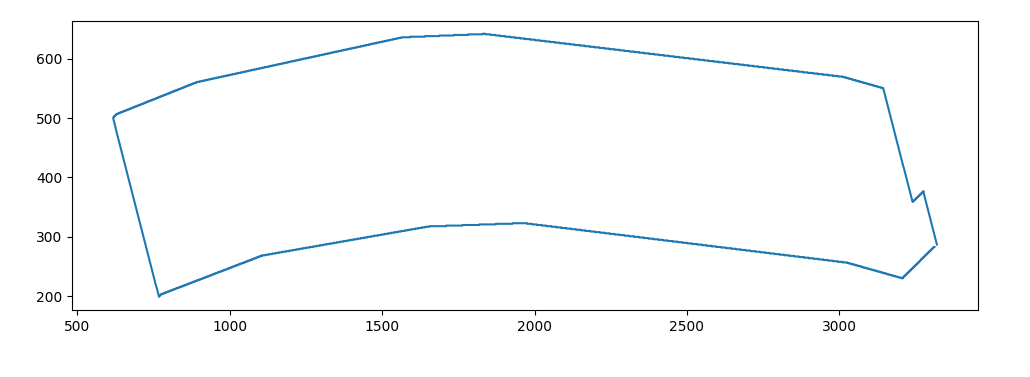
Next, I had to extract the actual numerical values from the G-code strings, which would serve as the basis for further computations. To do this I wrote a function that has the task to find any coordinates labeled with an X or Y in the G-code lines and gather them into two separate lists. The plot below shows the contour of the stringer if we plot the extracted coordinates:
Placing the Vacuum Clamps
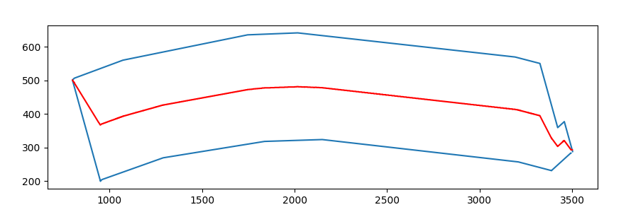
Let us now look at the real challenge of this project, which was to find a way to position the vacuum clamps on the machine table and how the clamps had to be shifted within the workpiece. My idea was to re-render the contour of the workpiece to fill in the missing values because as you can see in the G-code example above there are big gaps between the points of the original contour. The fine contour is then used to find the position of the clamps inside the workpiece.
My algorithm operates based on the following principle. First, a fictitious line is calculated using the centroid coordinates of the staircase component.
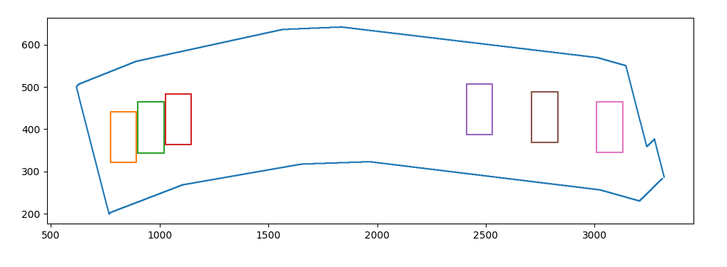
Then, points on the centroid line are sought for the centroids of the two outermost clamps until the distance between the clamps and the contour of the staircase component reaches 4cm.
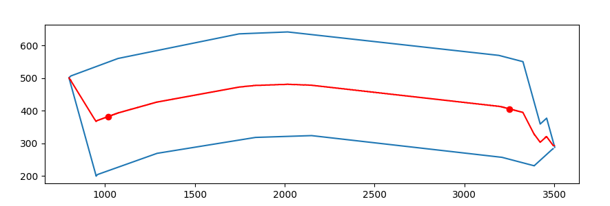
If we now plot the clamps, this first step looks like in the image below:
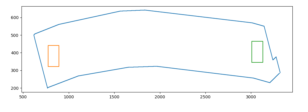
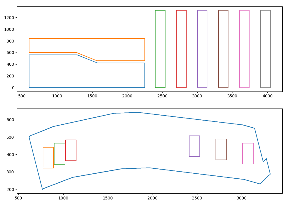
The remaining clamps are then placed on the centroid line, offset by the width of one clamp. This results in three clamps on the left and three clamps on the right, as a workpiece is always secured with exactly six clamps.
As you may have noticed, the clamps on the right have a different spacing than the ones on the left. If we plot the machine table beside the stringer it should become clear why this is the case.
It would have been great if the project was finished by now, however, due to the complex machine table, a total of four different algorithms had to be developed since the staircase components can have lengths ranging from 50cm to 6m and sometimes require significantly different positioning of the vacuum clamps within the workpiece and on the machine table. We will look at the different configurations at the end of the article.
Positioning on the Machine Table
After calculating the clamping positions, a suitable spot on the machine table had to be chosen. This calculation also depends on the length of the staircase components. In the next step, the zero offsets and the measurements for clamp and raw workpiece placement are calculated. Finally, a plot is made with the positioning of the workpiece relative to the vacuum clamps and the positioning of the vacuum clamps relative to the machine table.
In addition, the plot, which is output in the form of a PDF in A4 format, shows the necessary zero offsets that are fed into the CNC control panel. A finished computation gives a plot like the one below:
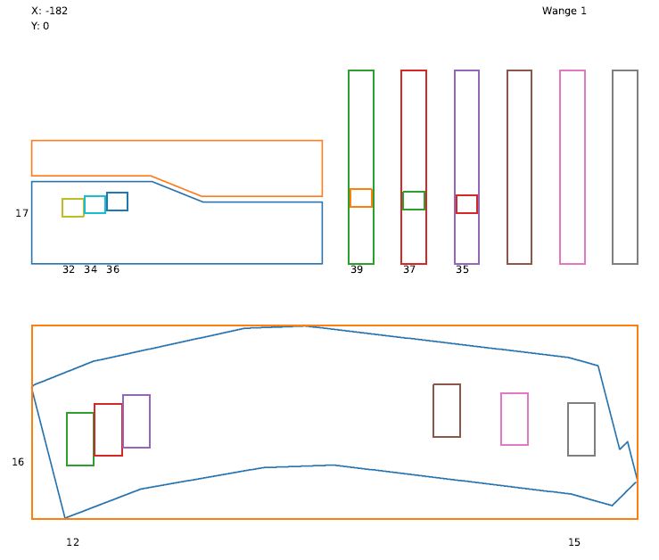
As already mentioned we will also look at the other possibilities of workpiece placement which are showcased in this PDF file.
Conclusion
This project will always have a special place in my heart as my first real attempt at developing an actual useful application. Ironically the project probably features the ugliest code that I have ever written but on the other hand, has also created the most value. The application could prevent a thirty thousand euro investment and has effectively reduced the time it takes to process one workpiece by around 25 percent. Additionally, working on the machine is now less error-prone, and training new employees has become faster.
In the years since I developed the positioning script I always played with the thought of refactoring the code, but given the time it would take to entangle the code and the fact that it really works flawlessly so far, I couldn’t really bother. Of course, you can have a look for yourself, as the code is hosted on GitHub.